Going with the (Mold)flow
- Team Blogger
- Apr 15, 2020
- 3 min read
This week we worked on finalizing our design such that all the parts are well-designed for manufacturing (i.e. the molds are machinable and there are no defects in moldflow simulations).
A summary of our MoldFlow analysis can be found in this spreadsheet:
https://docs.google.com/spreadsheets/d/1t0zIzyijaqvZMKfDPwDzt7lVIy8b_57oCm1KYRi5v5U/edit?usp=sharing
Additionally, here is a link to the presentation slides summarizing the analysis:
https://docs.google.com/presentation/d/1qdmu2D169kpOOTYFGlEnhdgKtrcb-pp86rpXeeodeb4/edit?usp=sharing
Apple Top
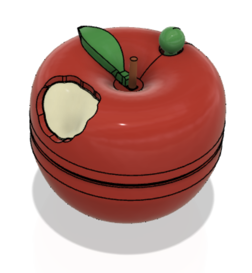
The bite mark in the apple top shell was initially modeled such that the extrude cut was coming at angle. However, the resulting mold would not be machinable with the 2.5 axis machines we have access to. So we revised our design such that the bite mark consists of two perpendicular cuts. We also added fillets on the cusps of the bite mark arcs because they wouldn't be machinable otherwise. Also, to help with part release and prevent tool wear, we added a 1 deg draft to the features that would require shutoffs.

After conducting moldflow analysis with the LMP settings, we found that the shrinkage percentage is 0.99%, so we scaled our part by 1% when creating the mold.

Apple Bottom
Running the MoldFlow analysis for this part showed us that there aren’t any major issues to be concerned about when injection molding it. The only concern is that there may be a couple air traps on the opposite edge from the gate. There weren’t any sink marks, weld lines, or other defects in the analysis though. When we reran the analysis using “ideal” settings, including the optimized molding window and gate location from the gate advisor, the part had a higher overall quality. However, it seemed like there were way more air traps along the bottom edge since the advised gate location was at the top of the shell. Here is an image of the shrinkage along the part:

Overall, with the LMP settings we got a shrinkage percentage of 0.9893% so we scaled our part by 1.0108 when creating the mold.

Questions about mold CAM:
What is the best way to machine the core for the apple shell to ensure it’s as smooth as possible?
What tool is best for this?
Inner Body
Some fillets were added to improve mold machinability. We have not design any features for insert molding the nut, yet.
In Moldflow, with the LMP settings, we got a shrinkage percentage of 98.78% So we scaled our part by 1% when creating the mold.
Currently, the mold looks like this:

Stem
There was some discussion on how to best orient the part with respect to the mold. We decided that machining would be easier if the stem is perpendicularly oriented (such that the length of the stem is sticking into the mold instead of along the mold horizontally).
In Moldflow, with the LMP settings, we got a shrinkage percentage of 98.70% So we scaled our part by 1% when creating the mold.

The final mold looks like this:

Leaf
While making the mold, we realized that the part is thinner than the ejector pin diameter. To insure better ejection, we increased the thickness of the part. To ensure mold machinability, we added fillets to the part.

From Moldflow analysis we learned that there is an undercut feature and that the shrinkage would be 98.5%. Using the gate advisor tool, we found that the ideal location would be on the underside of the leaf. However, when experimenting with creating a multi-cavity mold in Moldflow Advisor, we found that both the initial configuration of the parts and the configuration adjusted for the ideal gate location did not exhibit the best quality predictions. We experimented with several configurations and found that the vertical orientation with star runners had the best quality prediction, as seen in the figure below.

We also found that the shrinkage was worse when we ran the analysis on the multi-cavity configuration than on the single component, as seen in the figure below (left: single, right: multi). Instead of the initial scaling factor of 1.6% we will use 2%.

Given all of the insights from Moldflow, this is our finalized mold design:

Questions about mold CAM:
~3 hours machine time - how to minimize machine time?
Currently using 1/16” ball end mill. Should we increase the thickness of the part so that we could use 3/32” or ⅛” mill?
Ejector pin holes -- What is the best tool to use for this?
Runner design -- Currently using a ¼” ball end mill because I assumed that a larger runner would be preferred. Should we use the ⅛” mill instead?
Here is a picture of our up-to-date assembly:


Comments